
Page 59 - EQTips_Eng
P. 59
IITK-BMTPC Earthquake Tip 29
What are the Essential Features of Confined Masonry Houses? page 2
beams above and below it. Earthquake behaviour In tie-columns, at least 4 deformed steel bars of 10
improves with the number of fully-confined masonry mm diameter should be provided, and tied with 6 mm
walls. For good earthquake behavior, at least a diameter mild steel ties at 200 mm centers (Figure 6a);
reasonable wall density should be available of fully closely spaced ties are required in top and bottom
confined masonry (as a percentage of plinth area of the portion of a tie-column, with spacing of 100 mm. Ties
building) in each plan direction of the building; this should have 135° hook ends. In RC tie-beams,
depends on a number of factors including the expected minimum reinforcement to be provided is somewhat
ground acceleration, number of storeys, and masonry similar.
compressive and shear strength. This reasonable wall Constructional Guidelines
density varies from 2% to 5%. Minimum depth Using quality materials, ensuring good workmanship
(height) of RC plinth beams should be 300 mm. and faithfully implementing architectural and structural
Many options have been practiced with regard to guidelines are vital in construction of CM buildings. For
foundations of CM houses, namely RC tie-column improved earthquake performance, the interface
starts from (1) plinth beam (house has no foundation between masonry walls and tie-columns should be
beam), (2) foundation beam (house has plinth beam), toothed, i.e., bricks of masonry courses are staggered at
and (3) foundation PCC (house has no foundation the interface with tie-columns (Figure 5a). This ensures
beam, but plinth beam is used). Option (3) is used that masonry walls are held snugly between tie-
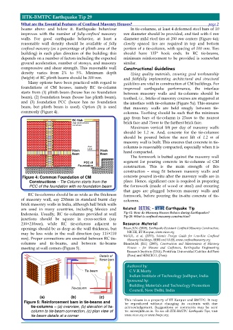
commonly (Figure 4). columns. Toothing should be such that the minimum
gap from bars of tie-column is 25mm to the nearest
RC Slab
Slab reinforcement brick face and 75mm to the farthest brick face.
not shown Maximum vertical lift per day of masonry walls
should be 1.2 m. And, concrete for the tie-columns
should be poured before the next lift of 1.2 m of
masonry wall is built. This ensures that concrete in tie-
Floor columns is reasonably compacted, especially when it is
Plinth Level Plinth hand compacted.
Beam Beam
The formwork is butted against the masonry wall
PCC of segment for pouring concrete in tie-columns of CM
Foundation construction. This is the main strength of this
construction – snug fit between masonry walls and
Figure 4: Common Foundation of CM concrete poured in-situ after the masonry walls are in
Constructions – Tie-Column starts from the place. Hence, significant care is required in preparing
PCC of the foundation with no foundation beam the formwork (made of wood or steel) and ensuring
that gaps are plugged between masonry walls and
RC tie-columns should be as wide as the thickness formwork, before pouring the in-situ concrete of tie-
of masonry wall, say 230mm in standard burnt clay columns.
brick masonry walls in India, although half brick walls
are used in many countries, including Mexico and Related - Earthquake Tip
Indonesia. Usually, RC tie-columns provided at wall Tip 12: How do Masonry Houses Behave during Earthquakes?
Tip 28: What is confined masonry construction?
junctions should be square in cross-section (say
230×230mm), while RC tie-columns adjacent to Resource Material
openings should be as deep as the wall thickness, but Brzev,S.N. (2008), Earthquake-Resistant Confined Masonry Construction,
NICEE, IIT Kanpur, www.nicee.org
may be less wide in the wall direction (say 115×230
Meli,R., et al, (2011), Seismic Design Guide for Low-Rise Confined
mm). Proper connections are essential between RC tie-
Masonry Buildings, EERI and IAEE, www.confinedmasonry.org
columns and tie-beams, and between tie-beams Blondet,M. (Ed.) (2005), Construction and Maintenance of Masonry
meeting at wall corners (Figure 5). Houses – for Masons and Craftsmen, Earthquake Engineering
Research Institute (USA), Pontificia Universidad Católica del Perú
(Peru) and SENCICO, (Peru)
Details of
these bars
Authored by:
Tie-beam C.V.R.Murty
Indian Institute of Technology Jodhpur, India
Sponsored by:
Tie-column Building Materials and Technology Promotion
Council, New Delhi, India
(a) (b) (c)
This release is a property of IIT Kanpur and BMTPC. It may
Figure 5: Reinforcement bars in tie-beams and be reproduced without changing its contents with due
tie-columns – (a) overview, (b) elevation of tie- acknowledgement. Suggestions or comments may be sent
column to tie-beam connection, (c) plan view of to: nicee@iitk.ac.in. To see all IITK-BMTPC Earthquake Tips, visit
tie-beam details at a corner www.nicee.org or www.bmtpc.org.