
Page 107 - Jabalpur_EQ
P. 107
Lifelines
Chapter 6
normalized with their characteristic strengths, namely, 20 MPa and 415 MPa,
respectively. Corresponding to the design level of loading, that is, e /r =(53.6
MN m/ 35.1 MN)/8.825 m = 0.17, the entire section is in compression and con-
crete compressive stresses are below the allowable stresses according to IS: 456-
1978. Allowable stresses for the concrete and steel include 33.3% increase permit-
ted for seismic forces.
However, the flexural tensile cracking of the section is possible only when the
neutral axis moves in to the section and that happens at e/r = 0.55 for 1% rein-
forcement ratio. In other words, for the tension flexural cracks to appear the seis-
mic forces have to be at least (0.55/0.17 =) 3.24 times greater than the seismic
design forces prescribed by IS:1893-1984.
Efect of Reinforcement
If we neglect the effect of opening, which is very small in this case, it can be easily
shown that the kern of the section with no steel is a circle with radius equal to 0.5.
Even in that case the structure has a considerable overstrength. Since the exact
amount of reinforcement at the base was not known, a conservative value of 1%
was assumed in the above analysis. It should be noted that for the section to be
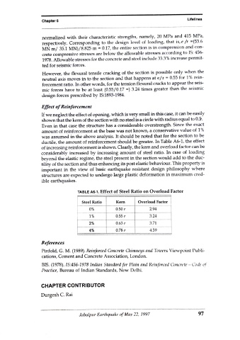
ductile, the amount of reinforcement should be greater. In Table A6-1, the effect
of increasing reinforcement is shown. Clearly, the kern and overload factor carn be
considerably increased by increasing amount of steel ratio. In case of loading
beyond the elastic regime, the steel present in the section would add to the duc-
tility of the section and thus enhancing its post elastic behaviour. This property is
important in the view of basic earthquake resistant design philosophy where
structures are expected to undergo large plastic deformation in maximum cred-
ible earthquakes.
TABLE A6-1. Effect of Steel Ratio on Overload Factor
Steel Ratio Kern Overload Factor
0% 0.50r 2.94
1% 0.55 3.24
2% 0.63r 3.71
4% 0.78r 4.59
References
Pinfold, G. M. (1989). Reinforced Concrete Chimneys and Towers Viewpoint Publi
cations, Cement and Concrete Association, London.
BIS. (1978). IS:456-1978 Indian Standard for Plain and Reinforced Concrete - Code of
Practice, Bureau of Indian Standards, New Delhi.
CHAPTER CONTRIBUTOR
Durgesh C. Rai
Jabalpur Earthquake of May 22, 1997 97