
Page 106 - Jabalpur_EQ
P. 106
Chapter 6
Litellnes
Weight of staging, W3-4.17 MN
Total seismic weight, W= W+W2+W3/3 32.3 MN
and it is assumed to be lumped at 23 m from the base
Approx. calculation of structure's period
Young's modulus of reinforced concrete, E = 25 500 MPa
Moment of inertia of the staging section at the base, I 375 mf
=
Lateral stiffness of the staging (approx.), K - 1 960 kN/ mm
Lateral deflection of lumped mass due to a force equal to the seismic weight,
S = W/K =16.5 mm
. Period, T = 27/8/g =0.26 s
Calculation of Design Seismic Force
Seismic coefficient, Fo = 0.2 (Zone III)
=
Importance factor, I =1.5
Spectral acceleration for T=0.26 s and 5% damping (assumed), Sa= 0.2g
Horizontal Seismic coefficient, ah = (1.2)(1.5)(0.2)(0.2) = 0.072
Design base shear, V = (0.072)(32.3 MN) = 2330 kN
Design overturning moment, M= (2330 kN)(23 m) = 53.6 MN m = 5 460 t m
(Compare it with the original design value of 5 350 t m)
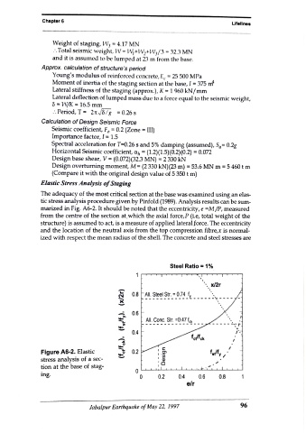
Elastic Stress Analysis of Staging
The adequacy of the most critical section at the base was examined using an elas
tic stress analysis procedure given by Pinfold (1989). Analysis results can be sum-
marized in Fig. A6-2. It should be noted that the eccentricity, e =M/P, measured
from the centre of the section at, which the axial force,P (i.e, total weight of the
structure) is assumed to act, is a measure of applied lateral force. The eccentricity
and the location of the neutral axis from the top compression fibre,x is normal
ized with respect the mean radius of the shell. The concrete and steel stresses are
Steel Ratio = 1%
x2r
08 All Steel Str. 0.74
0.6
All. Conc. Str. =0.47 c
-- -
0.4
Figure A6-2. Elastic 0.2
stress analysis of a sec-
tion at the base of stag
ing. 0 0.2 0.4 0.6 0.8
e/r
Jabalpur Earthquake of May 22, 1997 96